This section will describe various platforms. Some of them may exist at this
time, while others are fictional and may someday be manufactured. The intent is
to show the diversity of potential system topologies.
The systems described in this document include:
- A typical SMP system.
- The Alpha Wildfire system.
- The IBM Numa-Q system.
- The SGI Mips64 system.
- A system utilizing Multiple CPU on a single chip technology.
- A system in which CPUs and Memory are connected in aring.
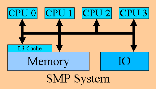
The following diagram shows a typical SMP system design, utilizing Intel x86 processors:

The typical SMP system includes multiple CPUs. The CPU typically contains an L1 cache.
The L2 cache is typically managed by the CPU but the memory for the L2 cache is external
to the CPU. The system may have an L3 cache which is managed externally to the CPU. The
L3 cache is likely to be shared by multiple CPUs. The system will also contain main
memory. The contents of main memory may be present in any of the caches. Hardware must
exist to maintain the coherency of main memory and the various caches.
Typical memory latencies:
- L1 cache hit:
- L2 cache hit:
- L3 cache hit:
- memory access:
The system also contains one or more IO busses, IO controllers attatched to the
IO bus, and devices attached to the controllers.
Currently searching for more information.
Any help identifying this information or a volumteer to write this
section would be greatly appreciated.
Please send any information to Paul Dorwin (pdorwin@us.ibm.com)
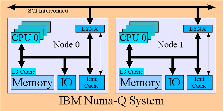
The IBM Numa-Q system design is depicted in the following diagram:

Each node in the system is simply a 4 processor SMP system. The Numa-Q utilizes
the Intel X86 CPU. Each CPU in the node contains a L1 and L2 cache. The node
contains an L3 cache which is shared by all processors in the node. The local memory
on the node contains up to 2 Gb of ram.
The node also contains a ??size?? remote cache, to cache data from remote nodes.
Nodes in a Numa-Q system are connected together via a Lynxer, which contains the
SCI interface (need more info on SCI).
memory latencies:
- L1 cache hit:
- L2 cache hit:
- L3 cache hit:
- local memory hit:
- remote cache hit:
- remote memory hit:
The Linux port to Numa-Q required modification to the way
in which the CPUs are addressed via the APIC. By default,
the APIC addressing of the CPU is flat, allowing for up to
8 processors on the system bus. The Numa-Q utilizes luster mode,
where the 8 bits are subdivided. Four bits are used to identify
a up to 16 nodes and 4 bits are used to identify up to 4 cpus
in each node. The Lynxer card is responsible for identifying and
routing cross node accesses.
Each node also contains 2 PCI busses. The first PCI bus contains
3 slots while the second contains 4 slots (VERIFY THIS)
At the time of this writing, Linux was verified to boot consistently
on 4 nodes containing a total of 16 processors. The Numa-Q work is hidden
behind CONFIG_MULTIQUAD, and the patches are being tested.
Work is underway to update the kernel to allow IO boards in all nodes.
Work is also underway to port discontiguous memory to the Numa-Q platform.
Currently searching for more information.
Any help identifying this information or a volumteer to write this
section would be greatly appreciated.
Please send any information to Paul Dorwin (pdorwin@us.ibm.com)
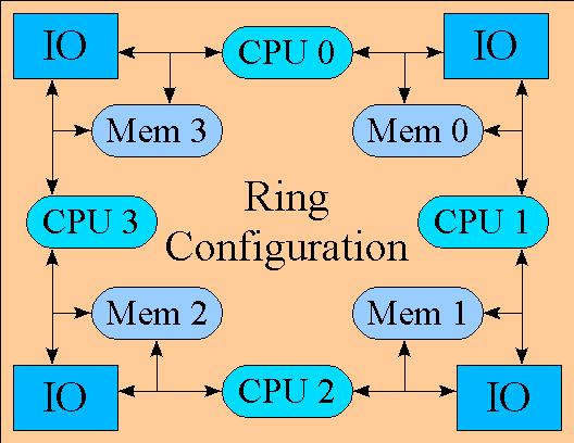
The following diagram shows a theoretical system in which each CPU connects
two independant memory nodes and each memory nodes connects to
two CPUs:

As can be seen, the end result of such a system is a ring configuration.
The following diagram shows a theoretical system in which a single chip contains
multiple CPUs:

All of the systems described here exhibit similar characteristics:
They all have Processors and some combination cache.
They all have some form of memory and IO.
Processors are separated from every other processors by some
distance.
However, there are major differences in the way that they are connected.
To restate this, they all have a unique topology.
Therefore, it is important to present an in-kernel infrastructure
which easily allows the architecture dependant code to create
an in-kernel description of the system's topology.
The section describing the in-kernel infrastructure will provide the
details of the proposed solution.
Here is a list of characteristics which should be able to be determined
from the system topology:
- How many processors are in the system.
- How many memories are in the system.
- How many nodes are in the system
- What is encapsulated in any given node.
- For any given processor:
- What is the distance to any other processor in the system.
- What is the distance to any memory in the system.
- How many cache levels exist and how large is each cache.
- For any given memory:
- What is the start pfn of the memory
- What is the size of the memory
- What processors are directly connected to the memory.


